There are many applications for spray nozzles. All require a fluid delivery system. SNP can design and manufacture a wide range of fluid delivery systems for our spray nozzles. Our approach is straightforward enough; we start with the nozzle that will deliver the optimal type of spray for the application and then work backwards from there to build the system that will ensure optimal performance. This approach ensures that the spray being delivered is correct every time.
The huge variation in the types of spray application we are asked to consult on means that a general “one size fits all” approach to fluid delivery systems is impossible. That being said, there are common components to all such systems. This guide goes through the various key components of a spray delivery system, what choices need to be made, and what some of the implications are for those choices. Throughout, we will focus on how system design choices are made to deliver the optimal spray for the application.
Fluid supply system
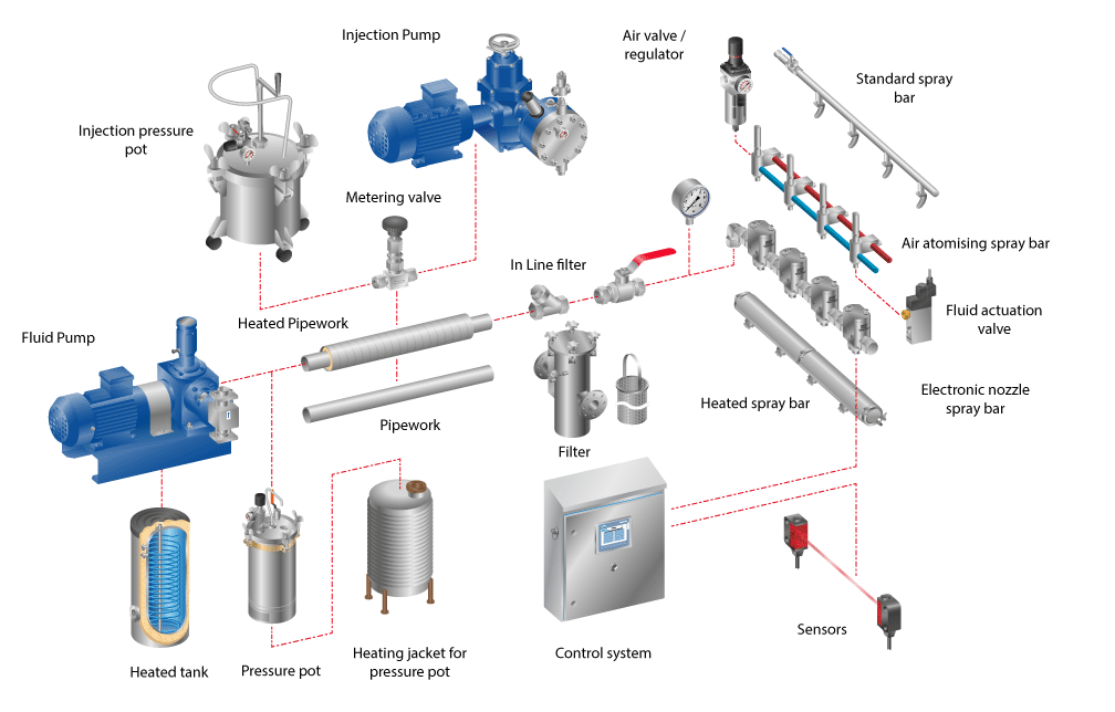
The main fluid supply system will either use a pump or a pressure pot to deliver moving fluid and pressure to the spray nozzles.
Pumps are more complex to operate and install, but can run continually as long as they are fed with a suitable fluid reservoir. There is a wide variety of pumps that can be used to supply spray nozzles. It is important to understand the application and the required spray characteristics when considering which pump to use. Of primary importance for any spray system is ensuring that the supply pump can produce sufficient pressure and flow rates so the nozzles can spray as specified.
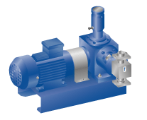
 Pressure pots are an alternative to pumps. With this fluid supply system, the liquid that needs to be sprayed is stored in a pressure vessel, and compressed air is pumped into the vessel. This puts the fluid under pressure, and so when the release valve is turned on, the fluid will move under pressure from the pot.
Pressure pots are a convenient way of delivering relatively small amounts of fluid. The pot will need to be refilled regularly, and this will result in some downtime.
Fluid Heating System
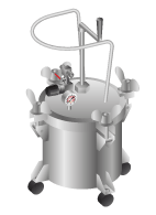
 If a fluid needs to be heated to spray properly, for example, it is very viscous at ambient temperature, then some form of heating system will be needed.
If the fluid is being delivered by a pump, then it is normally heated prior to entering the pump. This can be via in line 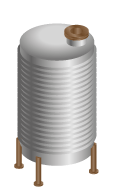 heater or from a heated storage vessel. In either case, the pump will need to able to handle the hot liquid.
If the fluid is being supplied via a pressure pot, then the pressure pot itself will be heated by a heating jacket. This will keep the liquid within the pot at the desired temperature. This can often be a simpler and cheaper design choice when compared to using hot liquid pumps.
Pipe and spray bar heating system
In some cases, heating the fluid at the source may not be sufficient to maintain the desired fluid temperature at the nozzle. As such, the pipework and spray bar may require insulation or heating to avoid heat loss or gain.
 This can be achieved by suitable lagging and/or trace tape heating to the pipework/spray bar. Careful analysis and testing will be required to ensure the desired end temperature is maintained.
Injection system (optional)
In many spray systems, additives need to be introduced into a water supply. Sometimes these will be premixed, but in other cases, the additive is injected into the water stream and mixing occurs in the pipework.
As with the main fluid supply, there are two ways this can be done: using a dosing pump or by a pressure pot system.
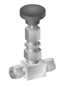
Injection control valve
An injection control valve will regulate the flow rate of fluid being injected into main water supply. This can be a simple on/off valve that activates when the main fluid supply is on. Or these valves can be more sophisticated and will vary flow depending on the flow rate of the mains liquid so as to keep the proportions of additive liquid the same.
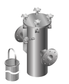
Filter
Spray nozzles, especially small orifice nozzles, are prone to clogging unless the fluid supplied is filtered correctly. There are many kinds of fluid filter available that will remove particulate from the fluid stream.
When selecting a filter, it is important to understand the level of filtration required, normally expressed as microns or mesh size. This will determine the minimum size of particles that can pass through the filter. In a spraying system, this should be matched to the filtration required by the nozzles which will largely be dependent on their orifice size.
Another consideration is the level of particulate likely to be present. This will determine the type of filter needed as heavily contaminated liquid streams will require filters with larger filter chambers so as to store the buildup of particles. If this is inadequate, the filter will regularly block, impeding fluid flow.
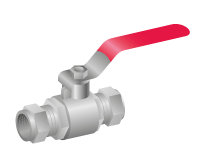
Spray bar isolation valve
The spray bar isolation valve allows for the entire spray bar assembly to be removed for maintenance. Normally this is a simple manually activated valve situated at the end of the spray bar.
Pressure gauge
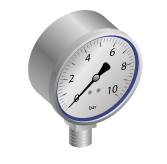 Having a pressure gauge right at the spray bar assembly means that we can monitor accurately the pressure “seen” by the nozzles. This is very important when diagnosing spray problems. If unexpected pressure losses are occurring, this will indicate that there are fluid supply issues further up the system such as a blocked filter or defective pump. But if the pressure is as expected at the entry point to the spray bar/lance then any spray issues will be likely to do with the nozzles themselves (perhaps they are worn or clogged). As such, a spray bar mounted pressure gauge is a vital diagnostics tool that often saves a lot of time and effort.
Spray bar system
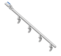
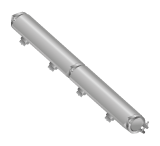
A spray bar is a pipe manifold that delivers fluid to multiple spray nozzles. There are two basic forms of spray bar.
A simple hydraulic spray bar will have a single fluid tube feeding many nozzles. These nozzles could have individual actuation valves or just all activate when fluid passes through the bar. The number of nozzles and the spacing between the nozzles will be determined by the application itself.
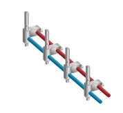 An air atomising or air actuated spray bar will have an additional compressed air feed running parallel to the liquid feed. This will deliver either atomising air for air atomising nozzles and/or air to actuate pneumatically controlled nozzles. In the latter, air is used to overcome a spring-loaded shut-off valve in the nozzle so spraying can commence.
Either option could require heating/lagging to maintain fluid temperature up to the nozzle.
Fluid control valves
 The on/off cycle of the spray nozzles will be controlled by a valve. This can be done in several ways.
If the spray application is continuous and a small-time lag for the spray to properly form is acceptable, then a single fluid valve controlling flow to the whole spray bar will be acceptable.
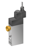
For nozzles that require accurate control or that require regular on/off spraying cycles, individual control valves may be required. These can be solenoid valves positioned just behind each nozzle or can be integrated within the nozzle body itself as with the EHP series of electrically actuated nozzles.
If compressed air is available, then air-actuated nozzles may be a good choice. These nozzles will have a spring-loaded shut-off system integrated into the nozzle body. This closes the nozzle unless compressed air is used to overcome the spring. As air is far more responsive than fluid, a single “master” compressed air valve can be used to control multiple nozzles' on-off cycles. For normal operations, 3 or 4 cycles per second are achievable, which is more than adequate for many stop/start spray applications.
NOTE: Both air atomising and simple hydraulic nozzles can be controlled by air actuation.
Air control valve (for controlling the air supply)
For nozzle systems that require air control, valves will normally be required. For air-actuated systems (nozzles that use pneumatic valves to control their on/off cycles), a solenoid control valve will be used to turn the nozzle system on and off. Multiple nozzles on a spray bar can normally be controlled in this way by a single valve. However, for very precise control, individual valves can be installed.
With air atomising nozzles, air is also required to mix with the fluid being sprayed to atomise it. This atomising air can be from the same source as the actuating air but, in some spray systems, we might need a separately regulated air supply, for example if the air pressure required for optimal atomisation is too low to actuate the internal pneumatic valve within the nozzle. In these cases, a separate control valve will be needed to regulate the air pressure down to the required level.
 Sensors
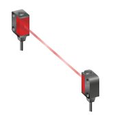
There are a wide variety of situations where sensors can be used to provide inputs to spray control systems. A simple setup would be to use a sensor to trigger spray nozzles to stop and start their spray cycle. Any type of sensor can be conceivably used as long as it can produce a signal to the control system (see below).
Control systems
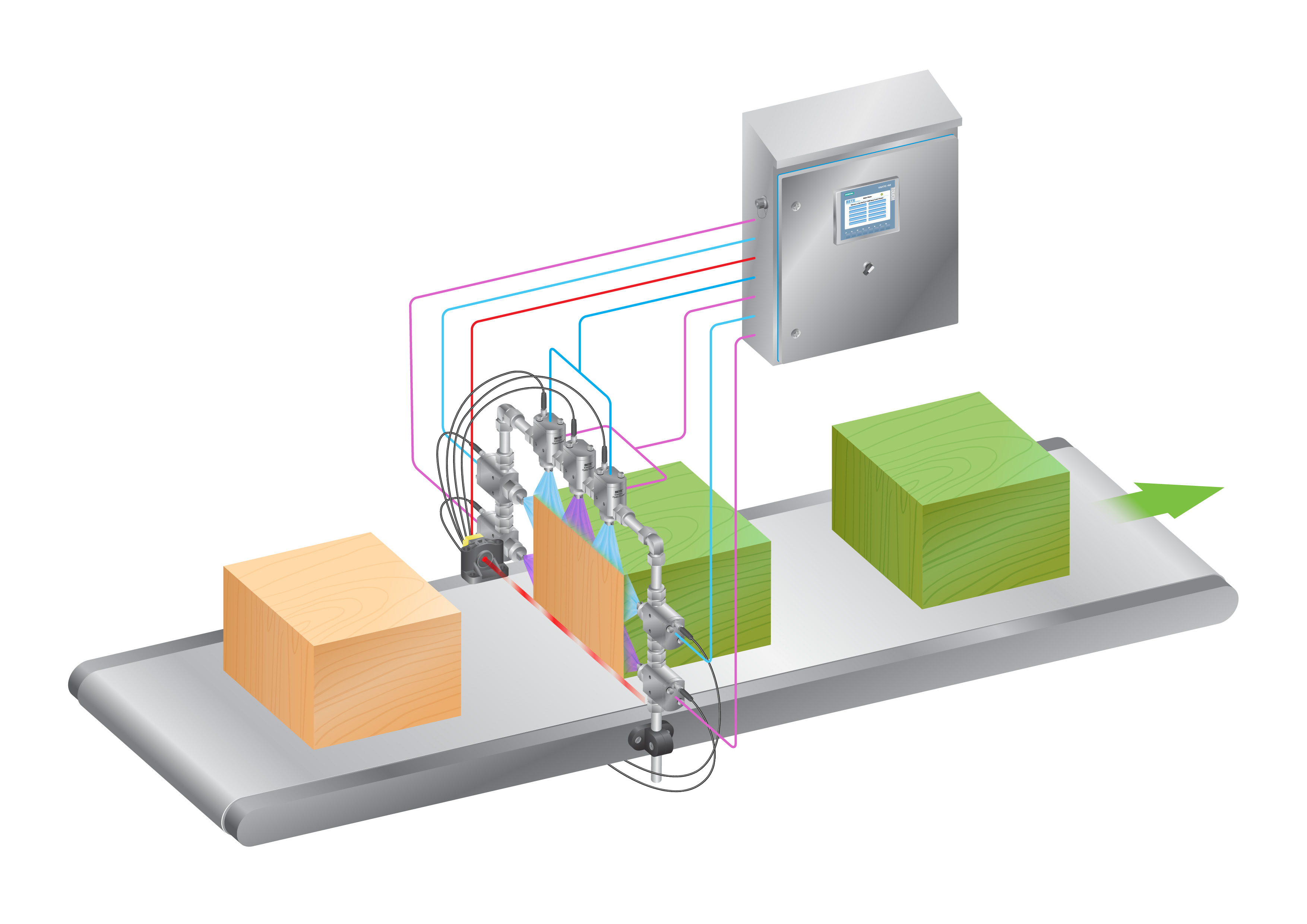 For many simple spray systems, very simple on/off control will be adequate. However, if we have cyclical spraying or different nozzles spraying at different times, an electric control system will be required to sequence the valves properly. For advanced techniques such as pulse width modulation, a sophisticated and specialist nozzle control system like the FlexFlow will be required.
There are many options for control systems, and their complexity and cost will vary depending on the sophistication and subtlety of what the spray nozzles are trying to achieve.